A guided wave radar level transmitter often gets attention only after a tank starts behaving badly. The level trend jumps around, maintenance gets called to the field, and operators lose confidence in the reading they use for inventory, transfers, and safe operation. In that moment, reliability teams need more than a definition. They need a way to decide when this technology is the right fit, how to install it so it stays stable, and how to troubleshoot it when the signal starts to drift.
Table of Contents
- Understanding Guided Wave Radar Principles
- Comparing Probe Types and Mounting Options
- Evaluating Performance and Selection Criteria
- Installation and Commissioning Best Practices
- Diagnosing Common Failure Modes
- Maintenance Calibration and Predictive Integration
- Industry Specific Applications
- Conclusion and Call to Action
Understanding Guided Wave Radar Principles
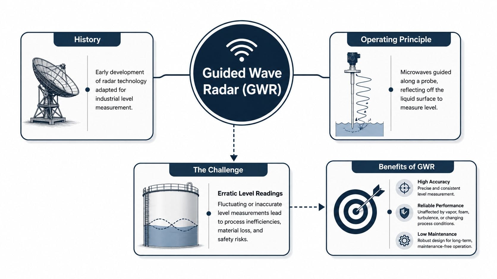
A storage tank that sends erratic level readings into the control system can waste hours of troubleshooting before anyone finds the root cause. Operators may blame the transmitter, the PLC input, or a process upset, yet the problem is often simpler. The measurement method itself matters, especially when foam, vapor, condensation, or interface layers make older level technologies unreliable.
How the measurement works
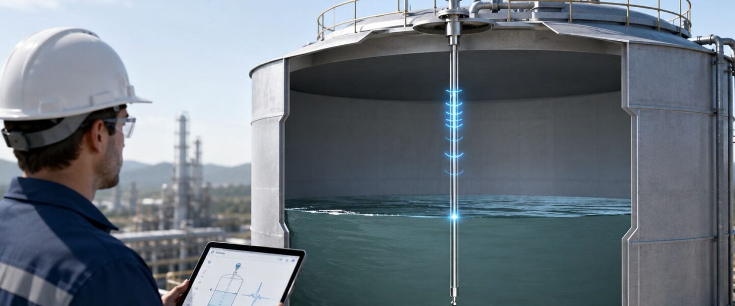
Guided wave radar, or GWR, is a time-of-flight method. A microwave pulse travels down a probe, then part of that energy reflects when it reaches a change in dielectric properties at the liquid surface. The transmitter calculates level from the return time, so it measures distance directly rather than inferring level from pressure, buoyancy, or conductivity. Early industrial radar systems emerged in the field in the mid-1970s, and the technology later moved through major product-line transitions as it became more common in process service (historical overview).
That direct-distance idea is why reliability engineers keep returning to GWR. The energy is guided along a probe instead of traveling through open air, so the signal is less exposed to conditions that distort other instruments. A manufacturer's product literature describes the same time-domain reflectometry principle for guided wave radar transmitters, where the reflected pulse travel time becomes the level value (guided wave radar transmitter principle).
Practical rule: if the vessel environment changes often, the best level device is usually the one that can still return a consistent echo, not the one that looks simplest on paper.
Why reliability teams care
In process plants, a level signal is rarely just a number on a screen. It affects transfer sequencing, inventory control, interface separation, and alarm response. GWR is valued because it can provide millimeter-level accuracy in hard applications, and a technical comparison for industrial level instruments places GWR and free-space radar at about ±2 to 5 mm accuracy. That accuracy matters when a few millimeters decide whether a vessel stays within operating limits.
GWR also has a strong place in interface measurement. A technical note states that part of the energy reflects at a material surface and the time difference is converted into a distance used to calculate either total level or interface level (interface measurement note). In an oil-water separator, that means the instrument can help operators see more than one layer, not just the top surface.
Reliability planning does not stop at the process variable. Hidden labor matters too, because the cost of a level problem often shows up in rechecks, nuisance alarms, and repeated site visits. A good maintenance review should ask whether the device is easy to diagnose, whether the probe can be inspected without major downtime, and whether the failure signatures are clear enough to feed into a CMMS work order. For a broader reliability perspective, acoustic methods can help diagnose some tank and vessel conditions, and a related overview is available in this acoustic monitoring resource. The point is simple, the best measurement choice depends on the failure mode you are trying to prevent.
Comparing Probe Types and Mounting Options
Probe choice is where many GWR applications succeed or fail. The electronics may be excellent, but the wrong probe style or a poor entry point can turn a stable transmitter into a nuisance. In practical terms, the probe is part of the measurement system, not a simple accessory.
Rod, cable, and coaxial probes
A rod probe is the cleanest fit for short vessels and applications with limited buildup. A practical engineering limit from one datasheet states that rod-probe GWR range can reach up to 6 m and handle media viscosity up to 500 cSt when the product is not adhesive (datasheet). That makes it a strong choice for sumps, short process vessels, and some day tanks where the probe can stay straight and clear.
A cable probe is better when the vessel is tall or when the probe needs to follow a longer measurement span. It flexes more easily during installation, but that flexibility also means it needs careful routing and enough clearance from internals. A coaxial probe offers a more enclosed measurement path, which can help in harsh service, but it also brings its own installation and cleaning considerations. In every style, the plant has to think about buildup, mechanical damage, and how often the probe can be inspected.
A probe that is easy to install but hard to keep clean can create more maintenance work than the older technology it replaced.
Mounting geometry and plant realities
GWR is a contact-based technology because the probe must extend into the vessel and contact the process environment, and proper mounting geometry affects measurement quality (mounting guidance). That means the nozzle location, flange compatibility, and the distance from agitators, ladders, and nozzles all matter. If the probe sits too close to an internal obstruction, the reflected pulse can become messy and the echo profile harder to interpret.
Grounding matters too, especially in noisy electrical environments. Maintenance teams should treat the installation like any other critical measurement point, with attention to shielding, stable mechanical support, and a repeatable entry arrangement. For teams standardizing procedure work, a shared workflow can help, and many plants pair that with dissolved oxygen sensor practices when they're tightening field-instrument discipline across the site.
The selection decision is rarely about which probe is “best” in general. It's about which one keeps signal integrity high while keeping maintenance access realistic.
Evaluating Performance and Selection Criteria
A level transmitter is easiest to choose when the plant asks the right question up front, what keeps the reading trustworthy without turning measurement into a maintenance project? A guided wave radar level transmitter earns its place in service when the vessel is hard to access, the process is messy, and the reading has to stay credible through normal plant variation.
Side-by-side selection logic
| Technology | Accuracy | Interference Susceptibility | Maintenance Requirements |
|---|---|---|---|
| Guided Wave Radar | ±2 to 5 mm in cited industrial comparisons | Generally less affected by foam, vapor, and changing media conditions because the microwave energy is guided along a probe | Probe contact means coating, damage, and cleaning still need attention |
| Non-Contact Radar | Also cited at ±2 to 5 mm in the same comparison | Can be attractive where no probe intrusion is preferred, but internal structures and some process conditions still matter | Usually lower mechanical wear because nothing extends into the vessel |
| Differential Pressure | Qualitatively lower for many level duties because it infers level from pressure | More sensitive to density changes and process variation | Requires impulse line and transmitter care |
| Ultrasonic | Qualitatively lower in difficult service | More vulnerable to foam, vapor, and turbulence | Often easier to mount, but less forgiving in unstable atmospheres |
The table gives the first filter. The reliability filter comes next. A plant can accept a fine-looking specification sheet and still lose value if the instrument needs frequent cleaning, inspection, or troubleshooting to keep the signal believable. That is why the ultimate comparison is not only accuracy, it is the full cost of ownership, including hidden maintenance work, access difficulty, and how often operators have to question the reading.
GWR often fits better than open-air methods when foam, vapor, or changing process conditions would make the signal less stable, because the guided path holds the measurement energy closer to the process interface. That does not remove upkeep, but it does change the failure pattern. Instead of chasing atmospheric disturbances, the team spends more time watching for probe coating, mechanical damage, or buildup that changes the echo profile.
Choosing the right application fit
Selection starts with dielectric properties, vessel geometry, temperature, pressure, and maintenance access. A low-dielectric product can be harder for some level methods to resolve, while a vessel packed with internals can make a non-contact device less practical. Recent product literature also shows GWR being positioned with stronger diagnostics and with wider temperature and pressure coverage, while noncontact radar remains attractive where probe-based instruments are less suitable (recent positioning note).
The maintenance question should be part of the selection from the beginning, not an afterthought. If the process is sticky, corrosive, or prone to buildup, the best choice is the one that still lets technicians inspect and clean the measuring path without creating long outages. That is also where a condition monitoring systems framework helps, because it keeps the decision tied to observed asset risk instead of habit. Teams that want repeatable handoffs should also build video SOPs for consistency, so operators and maintainers are looking for the same symptoms and documenting them the same way.
A practical rule helps here. If the concern is false reading from vapor or foam, GWR deserves a close look. If the concern is probe maintenance in a sticky service, another architecture may fit better. The best choice is the one that keeps the signal stable and the maintenance plan realistic over the full life of the instrument.
Installation and Commissioning Best Practices
A bad installation can make a good transmitter look faulty. Field teams often chase calibration for hours when the problem is a nozzle layout that crowds the probe, poor grounding, or a transmitter that is not running true. The fastest path to stable readings is to treat installation like precision mechanical work, not a quick instrument swap.
Start with mechanical placement
The probe has to sit where it avoids dead zones near the top and bottom of the tank and stays clear of internal obstructions. Because GWR is contact-based, the probe environment is part of the measurement path, and poor geometry can distort the echo profile. A nozzle that looks acceptable from the outside can still cause trouble if it places the probe too close to an agitator blade or tank wall, so the first check is always physical fit, not software settings.
Mount the transmitter squarely and verify that the probe is straight, properly supported, and matched to the vessel depth. If the process uses a cable probe, check that the cable will not sway into internals. If it uses a rod, confirm there is enough clearance for the full measuring span. A technician who rushes this step may end up using software tools to troubleshoot a mechanical issue those tools cannot solve.
Wire it cleanly, then commission it deliberately
Electrical noise can blur the picture during startup. Route the cable correctly, keep grounding consistent, and protect the signal path from unnecessary interference. Once the hardware is secure, configure the electronics with the actual vessel dimensions and the correct dielectric setting, then validate the echo profile during startup. That is the point where hidden installation issues usually surface, because the transmitter can finally see the process the way it will run.
For teams that need repeatable field work, it helps to build video SOPs for consistency so technicians follow the same mounting and checkout sequence every time. The commissioning record also needs a clear home in the control system, which is why many plants tie the signal path back to their PLC with SCADA architecture and use that record when a level issue shows up later in the CMMS.
Commissioning habit: if the echo profile looks noisy on day one, do not force the transmitter to learn a bad installation. Fix the installation first.
Diagnosing Common Failure Modes
Even a solid GWR installation can drift into trouble. The failure modes are usually practical, not mysterious. Coating changes the effective signal path, mechanical damage interrupts the probe, internals create confusing echoes, and electronics can drift or lose a clean connection to the control system.
What usually goes wrong
Probe coating buildup is one of the first things to check in sticky service. The layer doesn't need to be thick to change the reflected pulse enough to distort the reading. In chemical reactors and wastewater tanks, that can happen after process changes, cleaning delays, or altered product mix.
Cable breakage and probe corrosion are more straightforward, but they're easy to miss when the signal still moves a little. If the level value looks intermittently plausible, crews may assume the transmitter is fine and keep running. That's when a physical inspection pays off.
False echoes from nozzles, ladders, mixers, or tank internals can look like a real level return in the echo profile. When that happens, the instrument may lock on to the wrong reflection and present a steady but incorrect reading. That kind of failure is dangerous because it feels stable enough to trust.
How to troubleshoot without wasting time
Start with the reflectogram and compare it against a known-good installation pattern. If the pulse shape has changed, inspect the probe for contamination, damage, or misalignment. Use loop resistance checks and wiring verification to rule out electrical faults before replacing the electronics. If the process changed recently, confirm whether the dielectric properties of the product changed too, because that can alter reflection behavior.
The fastest diagnosis is usually not the most complicated one. Check the probe first, then the wiring, then the configuration, then the transmitter.
Root cause discipline matters here. A recurring false echo can lead crews to swap transmitters unnecessarily, while the actual problem sits in the vessel. A structured method such as root cause failure analysis helps teams separate a bad sensor from a bad installation, a bad process condition, or a bad maintenance practice.
Maintenance Calibration and Predictive Integration
A guided wave radar level transmitter may be sold as low-maintenance, but low-maintenance is not the same as no maintenance. Plants that get lasting value from it treat calibration and diagnostics as part of the asset strategy, not as a one-time setup step. That approach keeps the instrument useful after startup and keeps the maintenance team from treating it like a black box.
Planned work that prevents surprises
Routine work should include dielectric recalibration when the product changes, firmware updates when the manufacturer issues stability improvements, and probe cleaning when buildup starts to alter the echo profile. A clean probe is not just about accuracy. It also keeps the plant from chasing bad readings that waste operator time and cloud the actual condition of the asset. The interval should follow the service, not a calendar alone.
Diagnostics matter just as much. Product literature on level measurement points to advanced diagnostics and duty considerations as part of the selection conversation, while noncontact radar still has a place where probe-based instruments are a poor fit. That tells reliability teams something practical. Selection is no longer only about whether the transmitter reads level, it is also about lifecycle cost, maintenance burden, and how much attention the asset will need after commissioning.
Make the data useful in the CMMS
The biggest gain comes when echo profile data, calibration notes, and inspection findings are entered into the CMMS. Then planners can see whether a transmitter needs cleaning on a repeating pattern, whether the probe is slowly fouling, or whether a vessel is becoming harder to measure because process conditions are drifting. Alert thresholds should reflect actual failure behavior, not a generic service interval copied across the whole plant.
A practical predictive setup can also combine radar diagnostics with vibration and thermography routes when probe fouling is part of a wider process problem. JIT learning can help technicians respond faster when the work list changes, and a useful resource for that is JIT training for L&D. That kind of just-in-time support matters most when the field crew needs the same troubleshooting logic every time.
Industry Specific Applications
A guided wave radar level transmitter earns its keep in different ways depending on the plant, and that is where reliability thinking matters. The measuring principle stays the same, but the failure risk, inspection load, and hidden maintenance cost change from one service to the next. Good selection starts with the probe style, metallurgy, and cleaning plan fitting the process reality, not just the vessel tag.
Food and beverage, chemicals, oil and gas, wastewater
In a food and beverage tank, a sanitary rod probe often fits best because operators need steady level feedback through CIP cycles and product changeovers. Foam and agitation can make other technologies wander, while a guided probe keeps the measurement path more consistent. The maintenance team still has to watch for residue and confirm that cleaning practices are not leaving coating on the probe.
In a chemical reactor or storage vessel, corrosion resistance and product compatibility move to the front of the decision. Coated coaxial probes or other protected designs can help when the media is aggressive, but the team still needs to inspect for buildup and verify mounting hardware after service changes. In this setting, stable product or interface measurement can protect transfer discipline and reduce rework from bad level readings.
In oil and gas, interface measurement often drives the choice. A separator that must distinguish oil from water benefits from a transmitter that can calculate interface level as well as total level, which is the kind of duty a guided wave radar transmitter handles well. That makes the technology useful in upstream production tanks, midstream collection vessels, and similar separation services where a bad reading can lead to off-spec transfers, extra sampling, or manual intervention.
In wastewater, flexible cable probes are common in sludge or pumping applications where the probe span is longer and the media is less predictable. The challenge is not only measuring level, it is keeping the instrument alive in dirty service without creating too much inspection labor. In these plants, false echoes and coating usually matter more than raw accuracy on the specification sheet, because the maintenance burden grows fast when the probe needs frequent cleaning.
What the good installations share
Across industries, the stronger installations have three things in common. First, the probe style matches the vessel geometry. Second, the maintenance team knows what a healthy echo profile looks like, so a drifting signature does not stay hidden. Third, the CMMS record captures the pattern before the transmitter turns into a nuisance. That combination keeps the asset useful for longer and reduces surprise interventions that steal time from the crew.
The history of the technology matters here too. It was developed in the mid-1970s to solve a hard industrial measurement problem, not to chase novelty. That origin still shows up in the best applications today, where stable measurement and lower maintenance burden matter more than feature lists.
Conclusion and Call to Action
A guided wave radar level transmitter delivers the most value when the plant chooses the right probe, installs it carefully, and keeps its diagnostics in the maintenance workflow. The technology's direct distance measurement, strong interface capability, and resistance to foam and vapor make it a serious option for demanding vessels. Plants that treat it as a lifecycle decision, not just a device purchase, usually get better uptime and fewer nuisance calls.
A CTA for Forge Reliability. Start with a free reliability assessment and get a practical review of your level measurement risks, maintenance burden, and CMMS workflow gaps before the next bad reading turns into downtime.