A plant can run for months with an orifice run that looks fine on the faceplate, while the daily material balance slowly slips out of trust. The steam header total gets questioned, the gas transfer doesn't match the downstream ledger, or a batch reconciliation starts taking too long because someone has to explain why the number keeps moving. That's the trap with an orifice flow sensor, it usually doesn't fail in a way that screams for attention, it drifts into being believable enough to stay in service and wrong enough to cost time.
Reliability teams run into this all the time in refineries, chemical units, utilities, and steam systems. The metal plate didn't suddenly change into a different device, but the installation, impulse lines, plate edge, transmitter, or process conditions changed around it. The result is a flow signal that still looks orderly on the DCS while the plant starts making decisions from a number that no longer deserves that confidence.
Table of Contents
- When an Orifice Flow Sensor Quietly Stops Being Honest
- How an Orifice Flow Sensor Actually Works
- Key Parameters That Decide Sizing and Accuracy
- Installation and Tap Location Best Practices
- Common Failure Modes and How to Spot Them
- Orifice Flow Sensor vs Other Metering Technologies
- Integrating Orifice Flow Sensors with SCADA and Monitoring
- Maintenance, Calibration, and Revalidation Schedule
When an Orifice Flow Sensor Quietly Stops Being Honest
A refinery steam header can look healthy on paper and still be off in practice. The board sees a stable trend, the operator sees a reasonable number, and maintenance only gets pulled in after a monthly balance shows a mismatch that nobody can explain cleanly. That's how an orifice flow sensor becomes a reliability issue instead of a metering device.
The failure is often administrative before it's mechanical
The plate may still be centered, the transmitter may still power up, and the DCS may still display a clean signal. The problem is that the number no longer represents the actual service with enough confidence for a custody-style decision or a plant balance. In industrial service, orifice systems are valued because they're simple, standardized, and widely used in oil and gas, utilities, chemicals, and steam systems, but that same simplicity makes it easy to overlook gradual drift Primary Flow Signal on orifice applications and performance.
A good reliability habit is to treat the meter run like a rotating asset with a health condition, not like a static object. That means asking whether the reading is still trustworthy, not just whether the instrument is still alive.
Practical rule: if the meter's output is still smooth but the plant balance keeps taking extra effort, the problem is usually trust, not electronics.
Why the number can stay smooth while the process moves away from it
Differential-pressure measurement is easy to trend because the transmitter can keep producing a polished signal even when the assumptions behind that signal are weakening. A plugged impulse line, a damaged edge on the plate, or a changed upstream flow profile can all preserve the appearance of stability while biasing the inferred flow. In reliability terms, that's dangerous because wrong numbers that look normal rarely get challenged quickly.
That is why plants should think in terms of drift, revalidation, and evidence, not just calibration stickers. A meter that still “reads” can still be unfit for the decision it supports, especially in steam headers, fuel gas headers, and transfer lines where one bad run distorts more than one operating choice.
A chemical plant example makes it clear. A feed line to a reactor showed no alarming change on the trend, but the mass balance kept missing expectation after a turnaround. The orifice run hadn't failed dramatically; it had lost credibility because the installed conditions no longer matched the assumptions that made the original number useful.
How an Orifice Flow Sensor Actually Works
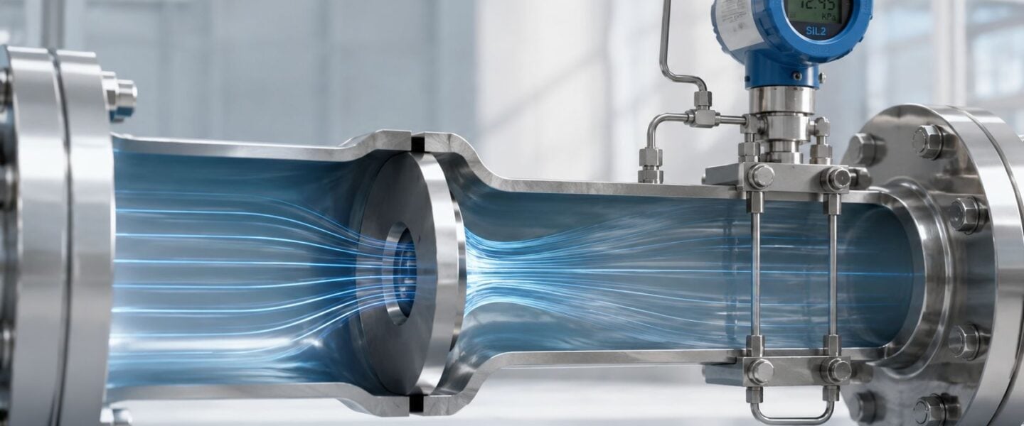
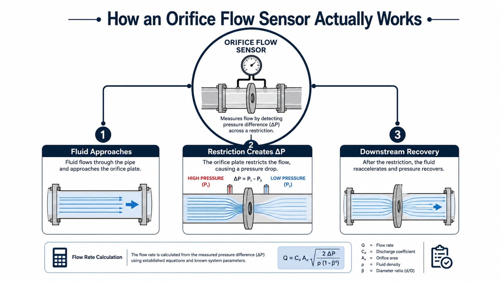
An orifice flow sensor measures flow by creating a controlled restriction in the pipe. As fluid approaches the plate, velocity rises through the opening and static pressure drops across the restriction, then some pressure recovers downstream. For turbulent flow, that pressure drop is proportional to the square of the flowrate, which is why the flow signal is derived from the square root of differential pressure Primary Flow Signal on orifice flow principles.
The restriction is the measurement
A simple way to picture it is water moving past a partly closed valve. The closer the opening, the harder the fluid must accelerate through the gap, and the larger the pressure difference becomes. The transmitter doesn't measure flow directly, it measures ΔP, the pressure difference between the upstream and downstream taps, then the control system or transmitter math converts that ΔP into flow.
That conversion depends on the discharge coefficient, which represents how real fluid behavior differs from the idealized equation. It also depends on the beta ratio, the ratio of bore diameter to pipe diameter. For a standard orifice plate flowmeter, beta ratio is typically selected in the range of 0.3 to 0.65, a practical design choice that balances signal strength against permanent pressure loss InstrumentationTools on orifice specifications.
The code-driven part matters as much as the plate
Orifice technology is standardized because the geometry and installation assumptions have to be controlled tightly for the measurement to remain useful. In custody-transfer-style service, API 14.3 is cited as giving mass-flow uncertainty around ±0.7% of rate under appropriate conditions, which is why orifice meters still sit in the same conversation as heavily calibrated flow technologies Plant Engineering on why orifice meters lead the way. That doesn't mean every field installation performs at that level. It means the standard exists because the method can perform well when the run is built and maintained correctly.
What the Reynolds range and beta choice really mean
The calibration window depends on flow regime, especially the Reynolds number, which expresses the balance of inertial and viscous forces in the stream. In plain terms, the orifice equation works best when the flow is in the expected turbulent region and the process conditions stay where the standard math remains valid. That's why the plate is not a free-form choice. It's a standardized device whose usefulness comes from matching the service to the code, not from improvisation.
Field insight: the plate is only one part of the measurement. The pipe, taps, transmitter, and signal processing all help decide whether the result is trustworthy.
Key Parameters That Decide Sizing and Accuracy
The sizing sheet can look elegant while still hiding a poor fit for the service. Reliability reviewers should focus on whether the chosen beta ratio, transmitter range, and expected uncertainty make sense for the actual operating window, not just for the design case. In a steam or gas header, a meter that is technically installed can still be a weak measurement if the signal is too small, the range is too wide, or the flow profile is unstable.
Beta ratio and transmitter range need to agree with each other
A smaller beta ratio increases differential pressure and usually gives a stronger signal, but it also increases permanent pressure loss. A larger beta ratio reduces pressure loss but can make low-flow operation harder to read. For standard orifice plates, beta ratio is commonly chosen in the 0.3 to 0.65 band, while the associated transmitter is often specified for 100:1 rangeability InstrumentationTools on orifice specifications.
That combination matters because an oversized transmitter can hide poor low-end resolution, and an undersized one can saturate too early. Reliability teams should ask one simple question during review, does the design support the actual operating band the plant uses most often, or only the nameplate case?
Installed uncertainty is not the same as the brochure number
A plate can be mechanically correct and still deliver a loose number in service. Typical installed accuracy is commonly cited in the ±2.0% to ±5.0% of rate range, depending on the code and plate design, while average operating conditions for standard orifice service are often described around 2% to 5% of reading Primary Flow Signal on applications and performance DwyerOmega on orifice plate flow meters. That gap between ideal and field performance is where reliability decisions live.
| Orifice Meter Performance and Limits at a Glance | ||
|---|---|---|
| Parameter | Typical Industrial Range | Reliability Implication |
| Beta ratio | 0.3 to 0.65 | Shapes signal strength and pressure loss InstrumentationTools |
| Transmitter rangeability | 100:1 | Wide range helps, but it doesn't fix poor low-flow signal InstrumentationTools |
| Installed accuracy | ±2.0% to ±5.0% of rate | Good enough for many services, not a substitute for validation Primary Flow Signal |
| Typical inaccuracy under average conditions | 2% to 5% of reading | Expect field drift unless installation stays healthy DwyerOmega |
| Custody-transfer-style uncertainty | ±0.7% of rate | Requires disciplined installation and maintenance Plant Engineering |
A good review process should also preserve the metadata around the meter, plate tag, bore, taps, calibration record, and the latest inspection findings. That kind of structured documentation is easier to maintain when teams borrow habits from good data governance, and Contesimal's 2026 best practices are a useful reminder that well-managed records make technical assets easier to trust.
Installation and Tap Location Best Practices
The best meter in the shop loses credibility fast if the run is built badly. Orifice measurement is sensitive to swirl, asymmetry, vibration, and bad impulse line practice, so the installation details matter more than many expect. A clean plate on a poorly prepared line can still deliver a biased result that looks polished on the screen.
Straight run and tap choice are part of the measurement, not the paperwork
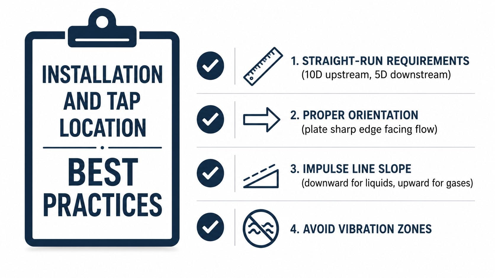
Orifice meters require long straight runs, about 60 to 80 pipe diameters upstream and 4 to 8 downstream, to reduce swirl and profile distortion DwyerOmega on orifice plate flow meter installation. That sounds excessive until a reducer, elbow, or partially open valve sits too close to the plate and starts shaping the flow field before the fluid reaches the restriction.
Tap location matters just as much. Flange taps are commonly used in the United States, corner taps are used where compact spacing or small pipe sizes demand it, and D and D/2 taps change where the differential pressure is sampled relative to the plate DwyerOmega. The more the taps move away from the plate, the more exposed the system becomes to pipe roughness and installation inconsistencies.
Impulse lines are often the weak link
Impulse lines should be routed so they don't collect gas in liquid service or liquid in gas service. They also need enough discipline to avoid temperature-induced drift at the DP transmitter and enough slope to keep the lines self-purging as intended. A plant can fix the plate and still keep bad readings if the impulse lines are partially blocked, water-filled, or leaking.
A 6-inch steam line is a common example. If a reducer sits too close upstream, the flow profile can stay distorted all the way to the plate, and the meter will read a value that is systematically wrong. The operator may never see a dramatic issue, only a persistent offset that becomes “normal” because it's been there long enough.
Practical rule: if the upstream piping looks crowded, assume the meter is being influenced until the run is proved otherwise.
The internal checklist many teams already use for other instrumentation is useful here too, especially the discipline behind a condition-based maintenance approach. The point is not to inspect on a calendar alone. It's to inspect when the run's behavior suggests the installation has stopped being representative.
Common Failure Modes and How to Spot Them
Field failures rarely announce themselves with a dramatic zero. More often, the DCS shows a believable trend while the plate edge erodes, the line fouls, or the transmitter zero walks off its original point. Reliability crews need a symptom-based mental model, because each failure mode leaves a different fingerprint on the reading.
Plate damage and buildup leave different signatures
Edge erosion or burrs often show up in dirty gas or steam service as a steady under-read or a reading that no longer reconciles with the balance. The plate edge is supposed to stay sharp, so when corrosion or erosion rounds it off, the discharge behavior changes. Fouling in liquids usually biases the meter in a different way, especially if deposits narrow the opening or create asymmetric buildup.
Flatness loss from water hammer is another ugly one. The plate may not look obviously broken, but even a slight warp can shift the flow coefficient enough to make the run untrustworthy. A quick pull and lay-flat check during a shutdown is often more useful than debating the trend graph for another week.
Impulse lines and transmitter drift show up on the screen
A plugged impulse line can freeze the signal, create noisy DP, or cause midnight jumps when a partial slug clears. A transmitter with slow zero drift often looks harmless until the reading is compared against a known no-flow condition or a second balance point. Those failures are easy to miss because the DCS still displays a real number, just not the right one.
- Steady under-reading: often points to plate edge wear, bore change, or fouling.
- Frozen flow or delayed response: often suggests plugged impulse lines or trapped liquid/gas in the tubing.
- Noisy DP: often tracks vibration, flashing, or unstable impulse line conditions.
- Step changes at odd hours: often point to intermittent blockage or transmitter zero movement.
The right response is usually simple. Inspect the plate condition, verify the bore, check for corrosion or grease, blow down or pressure-test the impulse lines, and compare the reading against a known balance point. A broader reliability program centered on condition monitoring systems helps catch these problems before they turn into recurring disputes over which number is right.
Orifice Flow Sensor vs Other Metering Technologies
An orifice flow sensor stays popular because it is rugged, standardized, and straightforward to apply. It also has real trade-offs that matter to operations, especially permanent pressure loss and lower confidence when conditions vary outside the intended window. Good meter selection is not about defending one technology, it's about matching the service to the consequence of being wrong.
Where the orifice plate wins
Orifice systems are mechanically simple and widely accepted in major process industries. They're also familiar to maintenance crews, which makes them easier to troubleshoot during a turnaround or after an upset. In custody-transfer-style and utility service, that standardization matters because the plant isn't just buying a device, it's buying a procedure that many people already understand.
A chemical plant fuel gas header is a good example. If the process is relatively clean and the operating window is stable, the orifice can be a practical choice because the maintenance model is clear and the parts are easy to verify. That advantage becomes more valuable when the site wants predictability more than novelty.
Where it loses ground
The permanent pressure loss is the obvious downside. The orifice's loss is about four velocity heads, while a venturi meter is cited at less than 0.5 heads Primary Flow Signal on applications and performance. That is a meaningful energy penalty in services where pressure margin is already tight.
Orifice systems also need long straight runs and clean installation conditions, while many alternative technologies tolerate different kinds of disturbance or lower maintenance effort. Turbine meters can be sensitive to wear, vortex meters to flow profile issues, Coriolis meters to cost, and magnetic meters to conductivity and service type. The right choice depends on the actual process, not on habit.
For teams working through automation and flow reliability decisions, a broader view of advanced process control software can help because the control strategy and the meter choice affect each other. A meter that underperforms in the actual operating window will also weaken the control response built on top of it.
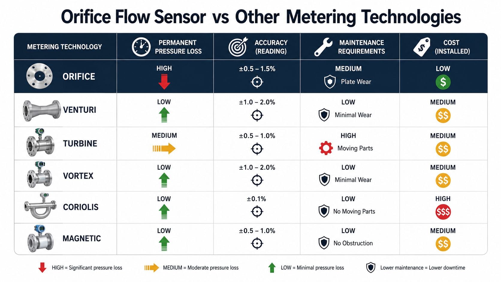
The practical takeaway is simple. Orifice plates remain a strong fit where durability, standardization, and accepted practice matter more than ultra-low pressure loss, but they are a poor default if the plant is paying a lot for lost head or trying to measure across wide and unstable flow ranges.
Integrating Orifice Flow Sensors with SCADA and Monitoring
A healthy orifice run still needs the control system to help catch drift. The DP transmitter should be configured correctly, the square-root extraction needs to happen in the right place, and the alarms should tell operators when the measurement has become suspicious rather than merely noisy. If that layer is weak, the plant loses one of the few early warnings it has.
The faceplate should show more than flow
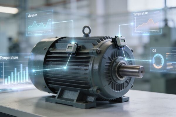
The SCADA or DCS faceplate should show raw DP, calculated flow, transmitter status, and any signal-health indicators available from the instrument. The most useful alarms are the ones that expose DP zero shift, unexpected differential pressure at no-flow conditions, and unusually noisy signal behavior. These are the patterns that often show up before a balance problem becomes obvious.
Square-root extraction can happen in the transmitter, PLC, or DCS, but it has to be documented clearly so technicians know where to troubleshoot. A maintenance crew chasing the wrong layer wastes time, especially when the signal looks normal at one point in the chain and distorted at another. That is why every critical run needs a clear tag history and a clean signal path, much like a well-structured PLC with SCADA architecture.
Trend against something independent
The best drift check is usually a second balance point. That can be tank level change, an upstream meter, or a downstream process mass balance, depending on the service. When the orifice reading starts to diverge from that reference, the team has evidence worth acting on before an audit or production review forces the conversation.
If the flow trend looks fine but the balance keeps slipping, trust the balance first and the meter second until the run is verified.
A practical SCADA screen for a critical orifice run should include the raw DP, calculated flow, alarm status, last calibration date, and a note of the most recent revalidation outcome. That simple context makes it easier for operators to escalate the right problem instead of treating every odd number as a control issue.
Maintenance, Calibration, and Revalidation Schedule
An orifice run stays trustworthy when it's inspected like a critical measurement asset. The plate, transmitter, impulse lines, and installed piping all need periodic attention, and the schedule should be tied to both turnaround windows and condition-based triggers. The most common mistake is waiting for a dramatic failure instead of acting when the evidence starts to weaken confidence.
What to check and when to pull the plate
Start with visual inspection of the plate edge and bore. Look for erosion, nicks, fouling, corrosion, and any loss of flatness. Then verify the bore dimension, confirm the plate orientation, and check the impulse lines for leaks, blockage, or trapped liquid.
The transmitter should get a zero check and span verification on a regular basis, especially if the flow reading has been challenged by a material balance. Blow down or flush the impulse lines where service allows, then confirm the signal returns cleanly. If the meter still disagrees with a reliable balance point, the run deserves deeper review rather than another temporary correction.
A plate should be revalidated or pulled when there's visible edge damage, measured bore growth, persistent balance error outside tolerance, or a process change that pushes the service outside the original operating window. For many plants, that aligns with a turnaround rhythm, while sensitive or high-consequence service may justify tighter condition-based checks. The routine discipline behind IP camera live streaming setup practices is a useful analogy here, because both disciplines depend on clear signal continuity, visible health checks, and fast recognition when the view no longer matches reality.
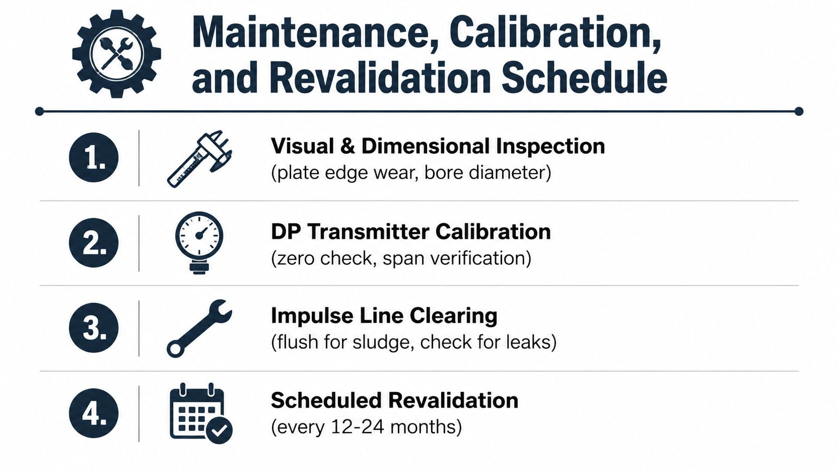
A practical schedule is straightforward. Inspect visually during turnarounds, verify the transmitter whenever the balance is challenged, clear and leak-test the impulse lines as part of routine walk-downs, and revalidate the run whenever the process or condition history suggests the old assumptions no longer hold. A plant that does that well stops treating flow as a guessing contest and starts treating it like an asset worth protecting.
If your plant depends on orifice runs for balances, steam accounting, fuel gas, or custody-style decisions, request a free reliability assessment from Forge Reliability. A focused review can benchmark the condition of your meter runs, identify the installations most likely to drift, and give your team a practical plan to restore confidence before the next audit or turnaround.